Pages

Sunday, December 28, 2008

Handling Wet Alumina Trihydrate


Probably, you have heard about Wet Aluminia Trihydrate. This type of Feed was difficult to process by regular handling. This article might help for those you re-design their feed tank for this mixture.

Preface
Alumina trihydrate is used in the manufacture of aluminum chemicals such as aluminum sulfate, aluminum chloride, aluminum fluoride, and sodium aluminate. It is also used as a fire retardent and flame suppressant filler in plastics, a polishing agent, and as a raw material in catalyst and zeolite production.

The Solution
Herman Purutyan, a senior project engineer with Jenike & Johanson, initially made a site visit to discuss the project plans, review the processing conditions and handling requirements, and see the material. The next step was to test a sample of the alumina trihydrate in our lab, duplicating the process conditions.

He found that the wet cake is cohesive enough to arch and form stable ratholes in funnel flow silos. Funnel flow is defined as the flow pattern where during discharge some of the contents in a silo remain stationary, while some move. Product flow takes place in a channel located above the outlet. Once this channel is emptied, if the material is cohesive, a stable rathole forms and discharge stops. In addition to this "no-flow" condition, funnel flow can result in product caking in the stagnant areas, reduced silo capacity (to that of the rathole), and structural damage due to asymmetric loads and high impact loads caused by collapsing ratholes.

Problems associated with funnel flow can be avoided by ensuring that a mass flow pattern develops in a silo. Mass flow is defined as the flow pattern where, upon withdrawal of any material, all of the contents of a silo move. To achieve mass flow, the sloping hopper walls must be steep enough and have sufficiently low friction to allow the material to flow along them. In addition, the outlet size of the hopper must be large enough to prevent arching.

For this particular application, he determined that a third flow pattern, expanded flow, would be most suitable. Expanded flow combines mass flow and funnel flow, and consists of a mass flow section at the bottom of the silo, extending up to a large enough diameter to prevent the formation of a rathole. Above this mass flow section, the silo is designed for a funnel flow pattern.

The ability of a material to form a stable rathole is a function of its cohesive strength. There is a maximum rathole diameter, DF (determined from tests), beyond which a rathole becomes unstable. In an expanded flow silo, the flow channel is forced to be larger than DF by using a mass flow hopper with a top diameter larger than DF. Although flow in the upper section will be funnel flow, the silo can be emptied since a stable rathole cannot form.

Herman recommendation for the expanded flow silo is shown in the figures. A mass flow screw feeder was recommended for discharging material from the silo. In order to achieve mass flow in the transition hopper, the feeder was designed to withdraw material uniformly from the entire outlet of the hopper. This was achieved by ensuring that the capacity of the feeder is increased in the direction of flow.

With mass flow occurring in the lower section of the silo, alumina trihydrate will flow along the hopper walls. Wear was a concern, as alumina trihydrate is an abrasive material. They conducted tests to measure abrasive wear on the selected hopper wall surface, and we calculated the wear life of the hopper walls at the critical areas where high loads and/or high flow rates occur. We found that the alumina trihydrate is not very abrasive on the recommended wall material, so the selected wall surface will last for many years.

The engineers also calculated pressures exerted on the silo walls by the stored bulk solid. They analyzed two different conditions: loads applied after the initial filling of the silo, prior to any material discharge, and loads after material has started to discharge (flow loads). Many people assume hydrostatic pressures for bulk material loading; however, this is generally not the case. The result can be inaccurate load assumptions at critical areas in the silo.

Tuesday, December 23, 2008

Interphex Convention

Interphex Show Preview

This year, Interphex was held at the Pennsylvania Convention Center in Philadelphia, Pa.

Interphex, the largest pharmaceutical conference and exhibition in the world, was feature cutting-edge technology in the area of life sciences, from drug development to manufacturing. Once again, this show shares a location with PlarmaMedDevice, the only comprehensive event to focus on the convergence of medical device, pharmaceutical and biologic industries.

To safely handle shear-sensitive cells, use this centrifuge

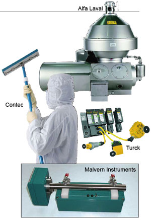
The Culturefuge 400 (photo) is a new production-scale disc-stack centrifugal separator designed specifically for primary clarification of shear-sensitive cell culture processing. The unit is capable of harvesting 20 – 30 m 3 of material from bioreactors in only a few hours, meeting the demand for processing at high capacities. Developed for larger scale applications involving mammalian cell cultures and other shear-sensitive biological material, the Culturefuge 400 has a hermetic outlet that prevents product contact with air, eliminating any possibility for foaming or oxidation. The hollow spindle inlet provides gentle acceleration of the feed liquid, minimizing lysis of shear-sensitive cells. Available in several configurations, it can be mounted on a fixed-base frame, which includes process and utility piping, automation and instrumentation for service and process liquids entering and leaving the separator. — Alfa Laval, Lund, Sweden

Morse

Booth 1334

This mop is designed for use in clean facilities

The EasyCurve Mop (photo) is designed for cleaning floors, walls and ceilings in cleanrooms and controlled environments. It consists of a flat, fabric-laminated mop head attached to a curved, stainless-steel frame, the EasyCurve provides superior performance, ease of use and effectiveness, according to this firm. Designed for pharmaceutical and medical-device manufacturing plants, hospitals, compounding pharmacies, and other critical or controlled environments, it is an ideal upgrade for applications where sponge roller and self-wringing mops are currently used. The EasyCurve is compatible with a wide range of disinfectants, solvents and cleaning solutions. — Contec, Inc., Spartanburg, S.C.

Booth 1034

Two new options improve this size measurement probe

The Parsum IPP-70 (photo, p.34D-1) inline particle-size measurement probe is now available with two new options that are designed to simplify regulatory compliance for pharmaceutical applications. Providing realtime particle-size analysis, the Parsum IPP-70 monitors and controls granulation, coating and spray-drying processes. The first new option allows for the provision of Installation/Operational Qualification (IQ/OQ) documentation together with a verification kit for checking measurement accuracy. The second option offers a unit with highly polished contact surfaces, and includes material traceability documentation. Size and velocity measurement is possible for particles, granules and pellets from 50 to 6000 µm in dia. With the ability to be inserted directly into a process line or unit and easily integrated with systems for automated control, it can be used to monitor gravity-fed, pneumatically-conveyed and fluidized streams. — Malvern Instruments, Bedfordshire, U.K.

Booth 1205

This modular RFID system is the first with built-in I/O

This firm now offers the first modular RFID system with built-in I/O capability. With BLident (photo, p.34D-1), users may add additional I/O modules, and up to 8 channels of RFID, plus additional discreet or analog I/O comprise a single node on the network. Built on the ISO155693 13.56 MHz HF standard, BLident can be integrated into existing platforms, and supports Profibus-DP, DeviceNet, Modbus-TCP, Profinet and EtherNet/IP. Standard non-programmable gateways and CoDeSys programmable gateways are available with either IP20 or IP67 protection rating. BLident data carriers are available with read/write intervals between 5 and 500 mm and use FRAM storage technology for virtually an unlimited number of write operations. It can read and write data simultaneously at 0.5 ms/byte and is capable of production speeds of 10 ms at a distance of up to 500 mm. — Turck Inc., Minneapolis, Minn.

Booth 652

These communication modules ensure efficient message delivery

An updated family of fiber-optic communication modules for ControlNet self-healing ring and dual self-healing ring applications is now available from this company. The single self-healing ring (EOTec 2C31) and dual self-healing ring (2C32) communication modules (photo) provide multiple communication paths between the various elements of the control system. They utilize Downstream Multicasting technology, so that, in the event of a failure on one communication path, communications are still maintained along a secondary path (or in the case of the dual ring, tertiary paths). This allows the transmission of incoming messages in multiple directions, ensuring that the message is directed towards all nodes in the ring while never being transmitted back to the point of origin. According to the manufacturer, these communication modules support the highest number of nodes and deliver up to 60% more optical power than competing models, allowing for the longer transmission distances between nodes. — Weed Instrument Company, Inc., Round Rock, Tex.

Booth 349

A tablet counter and more from this packaging firm

The RX-Fill (photo, p. 34D-2), a versatile tablet counter, is capable of counting product in manual, semi-automatic and automatic modes of operation. Also available from this company is the bottle Recoverx 1040, a solid dose product recovery system designed to allow the operator to recover product from containers of various shapes and sizes. The manual Recoverx, a manual-deblistering machine, requires no change parts and will also be on display. — BellatRx Inc., Point-Claire, Quebec, Canada

Booth 4207

Feed difficult-to-handle powders accurately

Available in pharmaceutical and industrial models, the MT12 micro-ingredient feeder (photo) accurately feeds free-flowing to difficult-to-handle powders at rates between 20 and 2,000 gal/h. Loss-in-weight (model KCL-SFS-MT12) and volumetric (model KCV-MT12) feeders are available for continuous or batch operation. These compact feeders are designed for easy disassembly, fast and easy cleaning and optional automatic refill. Typical applications include: feeding jet mills, tablet presses, continuous extrusion processes and accurate feeding of expensive micro ingredients. — K-Tron, Pitman, N.J.

Booth 1317

Handle high temperatures and pressures with this flowmeter

The Type 8045 Insertion Magflowmeter (photo, p. 34D-3) incorporates a stainless-steel finger and fitting to meet high-pressure and high-temperature requirements of instrumentation and automation applications. The unit handles medium temperatures (up to 230°F) and fluid pressures up to 230 psi. The measuring velocity range is 0.33 – 33 ft/s. The Type 8045 is compatible with pipe diameters of 0.5 to 16 in. It features a 4 – 20-mA output, as well as pulse and relay outputs. It can be used with a PLC with this company’s Type 2030 diaphragm valve, Type 8630 digital positioning unit coupled with the Type 2712, and the Type 8644-P. — Burkert Fluid Control Systems, Ingelfingen, Germany

Booth 317

Sunday, December 21, 2008

Developing A Health and Safety Program

By Gary Ganson, Certified Industrial Hygienist, Certified Safety Professional

EHS Group Manager, Environmental
Terracon
Lenexa, Kansas

Where to Begin?

Last month’s column focused on the importance of health and safety compliance and the all the resources that were available to help businesses, particularly small ones, meet their obligations to keep their workers safe. Compliance begins with commitment and a health and safety program tailored to fit the company, to blend with its unique operations and culture and to help employers maintain a system that continually addresses a focus on prevention of workplace injuries and illnesses. Every effective program should include management commitment and leadership, employee involvement, workplace analysis, hazard prevention and control, safety and health training and performance goals and measurement.

When OSHA comes in to evaluate your company, one of the first things they look for is a written health and safety program along with training documentation and MSDS (Material Safety Data Sheets), if applicable. But I never tell a client we’re creating a health and safety program just to be OSHA compliant, we’re creating the program because it’s the right thing to do. It’s also a good return on investment because preventing employee injuries saves the company money. Particularly for small or newer companies, avoiding downtime can make the difference in whether the company survives.

The Team

The larger the firm, the easier it is to designate a health and safety officer. The smaller the company and the fewer the employees, the easier it is for health and safety measures to be overlooked or missed.

Responsibility for employee safety always rests at the top with the owner or manager, but typically it is the first line supervisor who is most capable of keeping workers safe. They have direct day to day contact with the workers, and they need to be aware of what resources and tools are available. However, the safest companies are those where employers and employees work together to make safety and health a priority and a responsibility equal with production and quality.

This partnership can be achieved by involving employees in health and safety policymaking, committees and posting the company’s written safety and health policy for all to see. Management should show its commitment by investing time, effort and money in the company’s safety and health program, abide by all safety and health rules and hold regular meetings that focus on employee health and safety.

Thursday, December 18, 2008

New ceramic-membrane system doubles rate and slashes cost for dehydrating ethanol

Hitachi Zosen Corp. (Hitz; Tokyo, Japan) is commercializing a new membrane for a hybrid-distillation system (HDS) that is especially suitable for dehydrating ethanol and isopropanol. The HDS can produce 99.7 vol.% ethanol from ethanol-water mixtures with 10 vol.% H2O at a dehydration rate of 50 kg/m2/h/atm (at 130°C), which is more than two times higher than conventional ceramicmembrane processes, says the firm.

The membrane element consists of a porous alumina tube that is closed at one end. A thin zeolite film is synthesized onto
the tube, and the pore size is precisely controlled by proprietary technology to be around 10Å, which enables the element to act as a molecular sieve for the two alcohols. In the HDS, the mixture is fed to the outside of the tubes and the dehydrated water is removed from the inner side of the tubes.

The membrane is able to dehydrate ethanol- water mixtures with less than 30-wt.% water and, when combined with distillation, covers a wider range of mixtures. Hitz estimates that HDS can save up to 30% of the energy required to dehydrate ethanol, and the required installation space for the membrane unit is about half that needed for a pressure-swing-absorption unit.

Hitz has demonstrated the technology in a test plant with the capacity to produce 30 kL/d of ethanol, and plans to expand the production capacity (for the membranes) to 750,000 m.t./yr this year. The firm has also designed an HDS for producing 99.7 vol.% ethanol from a 10 vol.% ethanol feed, with a capacity of 50-million gal/yr.

Sunday, December 14, 2008

SNC-Lavalin Improves FEED Work Process with ASD OptiPlant

Dear Fellow, When I Searching on site about improved Feed system, i had found something that maybe you would to see. Please read this up. And tell me about your opinions.

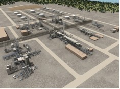
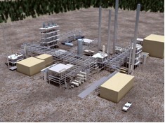
SNC-Lavalin Calgary has successfully incorporated ASD OptiPlant into the EDS Phase of the North West Upgrader Project and has achieved a 50% savings in piping design hours over conventional practices of applying a 3D detail design tool for the work to date. ASD Optiplant helped to verify and optimize the plot plan to produce a quality conceptual design with fewer resources.

PROBLEM Defined by SNC-LAVALIN
Phil Stephenson, Manager Plant Layout & Piping, at SNC-Lavalin Calgary, defined the problems in FEED work. (Similar issues exist with lump-sum bid efforts.) Prior to utilizing ASD’s solution, SNC-Lavalin’s options were to use any combination of manual sketching, 2D piping packages and 3D detailed design tools. All of these options required a large number of designers to work the layout while P&ID's were still under development. To keep up with the volume of work and still maintain the expected progress, the designers were not able to focus on the most basic functions of the group, namely to work several options of the plant layout for optimal results. The alternate tools are labor intensive, therefore the quality of the layout would suffer as too many designers were involved. It was also a struggle to keep up with the P&ID development. When moving into detailed design, there would be a significant amount of rework to bring the models to the level of quality required because the models built with detailed design tools were based on incomplete Reference Databases (RDB's).

SNC-LAVALIN OBJECTIVES

  • Improve the quality of FEED layout by using fewer and more senior layout designers
  • Allow the plant layout designers to focus on what they do best and not worry about the details of a detailed 3D model - SIMPLIFY
  • Improve accuracy of Material Take-offs (MTO's) and be less reliant on factors and allowances
  • Flexibility to work more than one plant layout option and provide MTO comparisons
  • Complete FEED with a layout and MTO which accurately reflect the P&ID's issued for FEED
  • Make use of FEED deliverables in detailed engineering with less rework, knowing the layout has been optimized
  • Avoid the use of detailed engineering tools in FEED
  • Avoid the need to setup a client-specific material database and all the setup associated with detailed 3D design tools
  • Avoid the need to source large numbers of designers for a short period of time with the required FEED skills
  • Change the mindset that an MTO from a detailed 3D design tool is somehow more accurate.

SCOPE
The North West Upgrader Project includes 18 units, 2000 items of equipment and 6000 lines. ASD’s OptiPlant software is utilized for plot plan development including: equipment modeling, structures modeling and automatic 3D interference free pipe routing. Accurate piping MTO’s and drawings for the units are automatically extracted by line-number and specification-driven totals. Major inline components such as control stations are placed at either user defined locations or selected automatically by the pipe router.


Each unit is modeled as a separate area or project and Rule-based Nozzles provided by Optiplant is used to assign Start and End point location for the lines. The lines are routed using a batch process and each area completed to date has an interference-free run of over 95%. The balance of lines are routed using the interactive online routing feature.

One of the major benefits of Optiplant noted during this process is efficient change management. During the course of the project, the plot plans and P&ID’s have been updated several times. These modifications are incorporated in the OptiPlant model rapidly and revised piping MTO’s are produced spending very few additional hours.

ASD’s Pipe Support Optimizer (PSO) was used to automatically locate supports and analyze the stress critical lines. The resulting stress reports and stress isometrics were validated within CAESAR on selected lines. By using PSO, the stress group was able to analyze 60% of the stress critical lines in half the normal time and with little re-engineering.

The project team continues to successfully demonstrated the application benefits of ASD’s FEED solution to automate the conventional work process as well as its’ cost-effectiveness with respect to design hours and material costs. If this effort was to be completed in a detail design system, the manhours required would have been at least 2 times greater and the changes could not have been incorporated.

ASD Optimized Plant Design (OPDTM) SOLUTIONS

OPTIPLANT CONFIGURATOR™

Knowledge based engineering application for optimizing plant layouts by automating 3D Plant Modeling and Pipe Routing. The OptiPlant work process involves integration with Front End Process engineering tools and costing tools to reduce FEED time, generate MTO’s and produce realistic plant walkthroughs in early stage of plant design. The quick 3D modeling of plant equipments & structures and basic pipe routing features available in the tool make it best for Proposal Engineering, Bidding and FEED stages of Plant Design.

PIPE SUPPORT DESIGNER™

It is an integrated piping stress analysis, support optimization and design tool. It provides automatic feasible pipe support Location and Type identification & support optimization along the piping route. It carries out complete piping stress analysis for thermal, gravitational and seismic loads along with code compliance checking.

“The piping discipline committed to use the Optiplant software for plot development and MTO’s. They successfully produced the deliverables to support FEED.

Saturday, December 13, 2008

Hallo World

Hello, in few weeks or month i will send all about chemical engineering update for you. In this blog of course. So i hope this information will help you, all the chemical engineering get more solution and Relevant information.
Sincerely
Radius